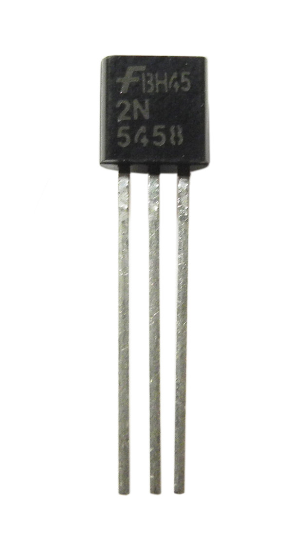
The IGBT (insulated-gate bipolar transistor) is a device for power control. The TFET (tunnel field-effect transistor) is based on band-to-band tunneling. The MODFET (modulation-doped field-effect transistor) uses a quantum well structure formed by graded doping of the active region. The HIGFET (heterostructure insulated gate field-effect transistor) is now used mainly in research. The FREDFET (fast-reverse or fast-recovery epitaxial diode FET) is a specialized FET designed to provide a very fast recovery (turn-off) of the body diode. It can be used as an image (photon) sensor. The DEPFET is a FET formed in a fully depleted substrate and acts as a sensor, amplifier and memory node at the same time. The DGMOSFET (dual-gate MOSFET) is a FET with two insulated gates. The MOSFET (metal–oxide–semiconductor field-effect transistor) utilizes an insulator (typically SiO2) between the gate and the body. The JFET (junction field-effect transistor) uses a reverse biased p–n junction to separate the gate from the body. One thing to realize is the write up above is for FET transistors (specifically JFET's) and will not work with the MOSFET transistors that we most often use. By applying a reverse-bias voltage between gate and source, pinch-off of the channel should be apparent by an increased resistance reading on the meter. This resistance should be relatively low (a few hundred ohms at most) when the gate-source PN junction voltage is zero. A resistance check from source to drain should yield the same value as a check from drain to source. Since the JFET channel is a single, uninterrupted piece of semiconductor material, there is usually no difference between the source and drain terminals. This connection will ensure that all residual voltage built up across the gate-channel PN junction will be neutralized, thus "opening up" the channel for an accurate meter test of source-to-drain continuity. The conductivity of the foam will make a resistive connection between all terminals of the transistor when it is inserted. However, if you don't know which terminals are which, the unpredictability of the source-drain connection may confuse your determination of terminal identity.Ī good strategy to follow when testing a JFET is to insert the pins of the transistor into anti-static foam (the material used to ship and store static-sensitive electronic components) just prior to testing. Of course, if you know beforehand which terminals on the device are the gate, source, and drain, you may connect a jumper wire between gate and source to eliminate any stored charge and then proceed to test source-drain continuity with no problem. Consequently, any meter reading of continuity through that channel will be unpredictable, since you don't necessarily know if a charge is being stored by the gate-channel junction. This can occur even when you're holding the JFET in your hand to test it. A stored charge across the capacitance of the gate-channel PN junction could hold the JFET in a pinched-off state without any external voltage being applied across it. Testing continuity through the drain-source channel is another matter, though. On the other hand, if meter indicates low resistance with both polarities, it means that the gate junction is shorted.


If the meter indicates high resistance with both the polarities, it means that the gate junction is open. When a JFET is checked as a diode (gate-to-channel junction) multimeter should indicate low resistance between gate and source with one polarity and very high resistance between gate and source with meter polarity reversed. In other words, a P-channel JFET would test differently than the N-channel JFET you tested. It doesn't take into account the polarity, nor the device type. Your test is missing reversing the meter leads to check in both directions (similar to how you would check a diode). I hope this helps! If there's anything inaccurate, please let me know! As an example, my shorted 13N10L tested at 1.0 Ohms. I spoke to Jim Rottendog and got a great answer I wanted to share.Ģ) Put your leads on the outer legs of the FETĪ good transistor should measure about 14,000 Ohms.
#Test fet transistor how to#
I knew how to test for a bad transistor, but I was not really sure how to test a FET properly, and the internet didn't yield anything awesome. I did a great job frying a transistor on a replacement Rottendog System 11B board and it has FETs instead of Darlington transistors (TIP102/136C, etc).


 0 kommentar(er)
